Resistivity Scans Pt 2
The Visible Ribs
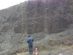
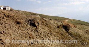
Looking at the surface of the upper section of the hull, which can be seen above the ground, vertical indentations which have the appearance of ribs can be seen protruding from the sides of the ship. Also the top edge of the hull shape can be seen to have a regular and evenly cut straight edge around the top of the hull.
After being exposed to the effects of the rain and snow which has fallen in this area for over the last 40 years, the erosion of the sides of this ship is quite different to that of the surrounding landscape.
The harder and more resilient material which seems to form the ribs and the inner surface of the hull, have not eroded as quickly as the softer infilling mud, making their shapes more pronounced.
The extra hardness of the material forming the rib indentations which are seen around the outer surface of the hull shape is also confirmed from the data of the resistivity scans. The resistivity images of the sides of the vessel show that the material forming these rib indentations continues below the ground surface and curves underneath the vessel, just as a rib timber would be expected to do.
Above the ground, the visible rib shapes which protrude from the sides of the ship each have a width of approximately 1 meter, (39.42 inches, or about 2 cubits), and are evenly spaced apart by about 3 meters. The fact that these rib structures lie on the outside surface of the hull shape eliminates the possibility that the hull shape could have been formed by erosion. Had the outer surface been worn away by erosion, any features on its outside surface would have been removed by the erosive action, leaving only a smooth surface.
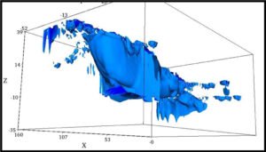
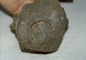
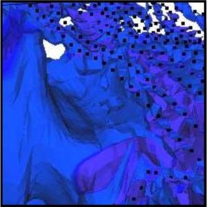
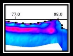
While we were still in Turkey and John was showing us some initial 2D scans, I got excited when we saw what looked like "ribs" in the below scan:
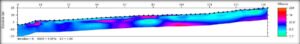
Here is a close up of that section:
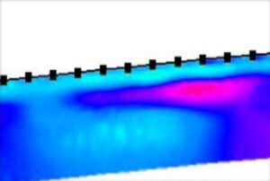
But I simply wasn't thinking correctly- ribs the size we see above the ground would not even be discerned when viewed on a scan on the entire length on Noah's Ark. What we were seeing is something much more exciting.
Much Larger Ribs Below the Surface
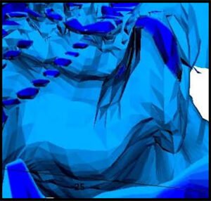
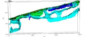
The visible rib like structures which can be seen above the ground, and which are directly attached to the inner hull of this object do not appear to be the main structure of this ship. The resistivity images showed that a series of much larger ribs exist which lie buried beneath the ground and surround the outside of this ship. These ribs are much more substantial and are spaced approximately 6 meters apart.
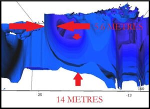
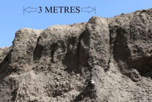
The above picture shows one of these ribs towards the back of the ship which is the lower end. The thickness of the upright portion of this rib measures 5.6 meters horizontally. Towards the centerline of the ship where the size of each rib is at their greatest, the rib thickness increases to approximately 14 meters. These ribs are massive!
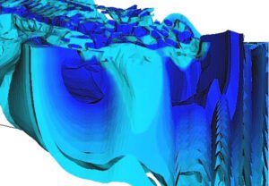
The lower section of each rib can be seen to have a semi-circular profile to both its lower outer and inner surfaces. They are also tapered with the thickness of the rib increasing in size towards the centerline of the ship.
The massive size of these timbers, though mind-boggling in size, must be kept in perspective with the overall size of the ship which required just such a structure to maintain the strength of the hull.
In modern ships this type of lower profile is often combined with slightly steeper upper sides, as are seen in these images of the ribs. When this shape of hull is also accompanied with a fin type of keel, the result is a hull shape which possesses a very low center of gravity combined with a high angle of heel.
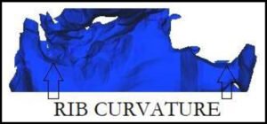
In the areas of the ship where the hull has not been damaged, the same curvature of the ribs is seen on both the left and the right sides of the ship.
The material composing each rib is slightly more conductive on its outer surface compared to further inside. This is exactly what would be expected to be found when a material such as timber is buried in mud and begins to petrify.
The outer surface of the material which is in direct contact with the mud, naturally begins to petrify first. However the innermost section of the timber is more protected and is able to resist the advance of the petrification the longest. This variation in the level of petrification will produce a difference in electrical conductivity throughout the timber, just as it is seen here.
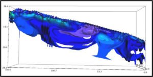
 The very large ribs that are deep in the earth can be seen here on both sides.(© John Larsen)
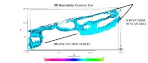
The Missing Portion of the Hull
Early in Ron Wyatt’s investigation of this site, he had found what he believed to be a portion of the keel of the ship embedded in the ground further up the mountain. He believed that this was where the ship had initially come to rest as the flood waters receded, and that sometime later the Ark had been caught in the lava flow which had torn the main section of the hull away from the keel and carried it down the mountain to where it is positioned today.
The central resistivity images that penetrated to the bottom of the hull, also show this bottom section of the hull shape is missing.
The Deck Joists
On the inside of the ship, opposite the ribs visible on the other side, equally spaced protrusions can be seen which Ron Wyatt believed were a part of the ships structure that had collapsed leaving the stumps of the timbers exposed.

Ron believed these were deck joists that once held a deck. He believed the weight of the lava caused the top portion of the ship to collapse, leaving these stumps.
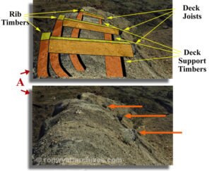
The resistivity scans reveal that this is exactly what Ron thought it was! The below scan was positioned directly over one of the ships's ribs. The image from this scan showed that an object of similar resistance to the rib material was connected horizontally to the rib and positioned exactly where the protrusion is seen inside the hull.

Possible Rooms at the Front of the Ark
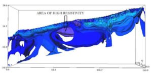
Pockets that are about the size of rooms and exhibit a very low resistivity (dark blue), form a regular pattern, at the front of the ship, where the middle deck is located.
When a room is still empty, the cavity cannot directly conduct the electrical current of the imaging equipment, and the output shows these areas with high levels of resistivity. However, if the room has become filled with mud, the combination of the mud and the water which is trapped and confined within the walls of that room, make the matrix within the room more conductive than the unrestricted and more freely draining, dryer soil around it.
Directly beneath these conductive pockets lies a flat layer of material that has a different electrical value to the conductive pockets and is consistent with the location of the floor of the middle deck.
If it is trapped water that is causing the high levels of conductivity, which are only seen on the middle deck, then the floor of the middle deck beneath these chambers, still must be intact. In this condition, the middle deck floor is able to prevent any water that is retained in the middle deck rooms, from seeping downwards. This is also a good indicator of how well preserved the timbers of the ship are in the front section of the ship, above where the hull has been damaged by the rock.
And this is where Ron found rooms and included them in his model.
Possible Ramp Connects All Three Decks
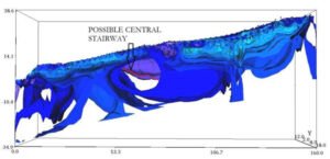
Along the exact centerline of the ship, the resistivity images identify an area of much higher resistance, (purple color), which is possibly an open cavity. The bottom edge of this cavity is inclined on a 35 degree angle relative to the decks of the ship, and slopes downwards like a central stairway where it connects the upper, middle and bottom decks.
Halfway down this stairway shaped area, at the same level as the floor of the middle deck, the angle of this stairway area flattens out to the same orientation as the middle deck, forming what appears to be a horizontal landing. The angle of the stairway shaped area’s floor then resumes, and descends down towards the floor of the bottom deck.
There are no other structures, or walls within the open cavity area and its orientation is aligned perfectly with the lengthwise direction of the ship.
The slope of the floor of this area is too steep for it to be used as a ramp. However, this angle is acceptable for a stairway. This is an interesting feature because having a more compact central stairway, instead of a ramp which would occupy more space, tells us that the useable deck space on the ship was maximized with the least amount of wasted space.
The bottom floor of this cavity penetrates down through the ship on a 16 degree angle relative to the decks of the Ark. The stairway descends through the ship in two stages with a horizontal landing separating each section of the stairway at the middle deck.
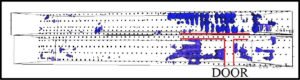
The Door into the Ark
Ron concluded from his numerous radar scans that the door into the ark was on the right side of the ark near the front. These scans verified that this is exactly where the door was.
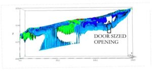
Leading from the door into the main corridor of the middle deck of the ark was also visible.
In Conclusion
The manner in which the hull has disintegrated is evidence that the hull of this ship had been traveling at some speed before it collided with the stationary rock outcrop.
The fact that the outer surface of the ship has broken up and that a section of the bottom of the ship appears to be missing also indicates that the keel section of the hull had already been torn away from the bottom of the ship before its impact with the rock. This has left a sizable hole in the bottom of the hull.
In order for this sequence of events to take place, the location of the original landing site of the ship should be expected to be found further uphill. It also must be within the area of the mudflow which could only have come from a volcanic source. Exactly as Ron Wyatt determined many years ago.
The resistivity scans revealed that this was a ship. Noah’s ship. There is no other explanation.

Welcome to the Ron Wyatt Archives. I'm Mary Nell (Ron's wife) and this site will attempt to fully document Ron Wyatt's work and discoveries. This website will be an ongoing project to document his work on all his various discoveries. Please check back often as new things will be added constantly.
| READ MORE |